Difference between revisions of "RocketDesignSpreadsheet"
(→Sec 4 Rocket Performance) |
(→Section 2 Oxidizer Tank Structure Mass) |
||
| (5 intermediate revisions by the same user not shown) | |||
| Line 21: | Line 21: | ||
== Section 2 Oxidizer Tank Structure Mass == | == Section 2 Oxidizer Tank Structure Mass == | ||
| − | In this section you specify the structural material of the oxidizer tank and the geometry of the oxidizer tank. The spreadsheet then uses the above information to calculate the wall thickness of the tanks, the total mass of the structural material for each oxidizer tank and the total structural mass of all the oxidizer tanks combined. | + | In this section you specify the structural material of the oxidizer tank and the [[Tank_geometries|geometry of the oxidizer tank]]. The spreadsheet then uses the above information to calculate the wall thickness of the tanks, the total mass of the structural material for each oxidizer tank and the total structural mass of all the oxidizer tanks combined. |
[[Image:RDS-Sec_2-Oxidizer_Tank_Structure_Mass.JPG]] | [[Image:RDS-Sec_2-Oxidizer_Tank_Structure_Mass.JPG]] | ||
| Line 32: | Line 32: | ||
The above ratios, let the tank be scaled by volume and thus avoid the need to respecify the tank dimensions each time it is desired to see how a change in volume effects the rocket. | The above ratios, let the tank be scaled by volume and thus avoid the need to respecify the tank dimensions each time it is desired to see how a change in volume effects the rocket. | ||
| + | |||
| + | (For more details on these ratios see: [[Tank_geometries]]) | ||
== Sec-3 Fuel Tank Structure Mass == | == Sec-3 Fuel Tank Structure Mass == | ||
| − | In this section you specify the structural material of the fuel tank and the geometry of the fuel tank. The spreadsheet then uses the above information to calculate the wall thickness of the tanks, the total mass of the structural material for each fuel tank and the total structural mass of all the fuel tanks combined. | + | In this section you specify the structural material of the fuel tank and the [[Tank_geometries|geometry of the fuel]] tank. The spreadsheet then uses the above information to calculate the wall thickness of the tanks, the total mass of the structural material for each fuel tank and the total structural mass of all the fuel tanks combined. |
[[Image:Sec_3-Fuel-Tank-Structure-Mass.JPG]] | [[Image:Sec_3-Fuel-Tank-Structure-Mass.JPG]] | ||
| Line 43: | Line 45: | ||
The final section of the spread sheet gives some overall performance of the rocket. In this part you specify the delta V you want to travel, the thrust per weight of the engine and the overall thrust per weight. The spread sheet then calculates the mass ratio and the approximate payload. The exit velocity of the fuel is chosen base on the above choice of fuel. Exit velocity is the product of gravity multiplied by the ISP.[4] | The final section of the spread sheet gives some overall performance of the rocket. In this part you specify the delta V you want to travel, the thrust per weight of the engine and the overall thrust per weight. The spread sheet then calculates the mass ratio and the approximate payload. The exit velocity of the fuel is chosen base on the above choice of fuel. Exit velocity is the product of gravity multiplied by the ISP.[4] | ||
| − | This section also attempts to calculate gravity losses (Also known as Gravity Drag) [5]. The optimal | + | This section also attempts to calculate gravity losses (Also known as Gravity Drag) [5]. The [[optimal ground launch flight path]] is such that the vertical component of the thrust cancels out gravity and the rest of the thrust is direct to horizontal acceleration. |
[[Image:RDS-Sec_4-Rocket-Performance.JPG]] | [[Image:RDS-Sec_4-Rocket-Performance.JPG]] | ||
| Line 79: | Line 81: | ||
[4] http://en.wikipedia.org/wiki/Specific_impulse#Specific_impulse_as_a_speed_.28effective_exhaust_velocity.29 - Relationship between specific impulse and ISP. | [4] http://en.wikipedia.org/wiki/Specific_impulse#Specific_impulse_as_a_speed_.28effective_exhaust_velocity.29 - Relationship between specific impulse and ISP. | ||
| + | |||
| + | [5] http://en.wikipedia.org/wiki/Gravity_drag - Wikipedia article on gravity drag. | ||
Latest revision as of 11:56, 15 August 2009
Contents
Introduction
The RocketDesignSpreadsheet was a spread sheet created by John Creighton with some help form Jumpboy for the purposes of trying to obtain better dry mass estimates, so that rocket performance (i.e. Mass Ratio) can be better calculated. The spreadsheet can be downloaded here:
http://www.geocities.com/s243a/mars/rocketDesignSpreadsheet.xls
The spreadsheet is described in further detail bellow. It is designed so you can make high level changes such as tank volume and overall thrust to mass ratio and it will scale the details of the rocket accordingly. This will let the user answer questions like:
-Do we can much efficiency in terms of ratio ratio by increasing the size of the rocket? -How do low thrust high ISP rockets compare to high thrust low ISP rockets.? -Are gravity losses a significant factor?
The Details are described further bellow.
Section 1 Tank Volumes and Fuel Mass
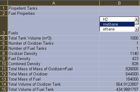
In the first part of the spread sheet you specify the tank volume and you select the fuel you want to use via a selection box. This value selected outputs an index of the selected value in the cell bellow the selection box. This cell is hidden. Cells further down uses this index to look up the values of the fuel and oxidizer density. You can also specify the number tanks for both the fuel and oxidizer. The remaining calculations, calculate the total volume of each tank, the total fuel/oxidizer mass contained in each tanke and the total mass of the fuel and the oxidizer.
Section 2 Oxidizer Tank Structure Mass
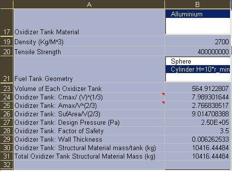
In this section you specify the structural material of the oxidizer tank and the geometry of the oxidizer tank. The spreadsheet then uses the above information to calculate the wall thickness of the tanks, the total mass of the structural material for each oxidizer tank and the total structural mass of all the oxidizer tanks combined.
Cmax/ (V)^(1/3) is the ratio of the maximum circumfrance to the cub root of the volume. Because the cross sectional area increases faster then the circumference, the cross section with the maximum cross sectional area, and simmillarly maximum circumfrance will be the point that determines the wall thickness of the Pressure_Vessel.
Amax/V^(2/3) is the ratio of the maximum area of a cross section of the tank to the volume raised to the power 2/3. This scaling means that these quantities are independent of the volume of the tank. It should also be noted that the maximum area of the cross section for a cylinder is taken as the cross section which is parallel to the axis of the cylinder. Now prof is given to show this is the cross section with the maximum area or that it is the critical cross section for design. However, it seems sufficient for design purposes when the factor of safety is included and the estimates for the tank mass are in good agreement with those of the space shuttle.
SufArea/V^(2/3) is the ratio of the surface area to the volume raised to the power of 2/3. This quantity is also independent of the volume of the tank for a given geometry.
The above ratios, let the tank be scaled by volume and thus avoid the need to respecify the tank dimensions each time it is desired to see how a change in volume effects the rocket.
(For more details on these ratios see: Tank_geometries)
Sec-3 Fuel Tank Structure Mass
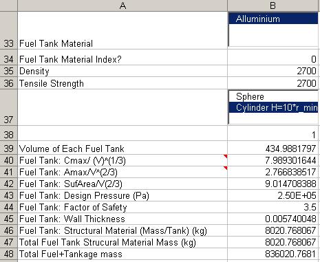
In this section you specify the structural material of the fuel tank and the geometry of the fuel tank. The spreadsheet then uses the above information to calculate the wall thickness of the tanks, the total mass of the structural material for each fuel tank and the total structural mass of all the fuel tanks combined.
Sec 4 Rocket Performance
The final section of the spread sheet gives some overall performance of the rocket. In this part you specify the delta V you want to travel, the thrust per weight of the engine and the overall thrust per weight. The spread sheet then calculates the mass ratio and the approximate payload. The exit velocity of the fuel is chosen base on the above choice of fuel. Exit velocity is the product of gravity multiplied by the ISP.[4]
This section also attempts to calculate gravity losses (Also known as Gravity Drag) [5]. The optimal ground launch flight path is such that the vertical component of the thrust cancels out gravity and the rest of the thrust is direct to horizontal acceleration.
Mass Breakdown of a rocket
A simple estimate of the rocket mass breakdown was given in [1].
Mass [kg]
Total mass 375
Propellant 300
Tankage system 57
Thrusters + plumbing 10.75
Miscellaneous 7.25
As you can see the majority of the rocket weight is in fuel.
Other Relevent Spreadsheets
http://www.paul.enutrofal.com/
Refferences
[1] http://www.lr.tudelft.nl/live/pagina.jsp?id=3784708c-c434-47f7-ae49-6f1f1d0d7114&lang=en - Gives The Mass Breakdown of a rocket.
[2] http://dunnspace.com/alternate_ssto_propellants.htm - Information about the rocket propellents was gathered here.
[3] http://en.wikipedia.org/wiki/Mass_ratio#Examples Contains a nice table for the mass ratio's of several rockets.
[4] http://en.wikipedia.org/wiki/Specific_impulse#Specific_impulse_as_a_speed_.28effective_exhaust_velocity.29 - Relationship between specific impulse and ISP.
[5] http://en.wikipedia.org/wiki/Gravity_drag - Wikipedia article on gravity drag.


